(Notes 1) CompSci 677 Distributed System - Editting
Disclaimer: This is my personal class notes for Distributed Operating System course taught at UMass Amherst. All images are taken from the free version of textbook and from slides. Notes contains extracts from textbook and from slides. This notes are for me to review the materials and for you if you are looking to review some concepts.
Lecture 1: High level concepts
4 important goals for a DS:
- Should make the resource easily accessible
- Should hide the fact that resources are distributed across network
- Should be open
- Should be scalable
Transparency:
DS tries to hide the fact that its processes and resources are distributed across multiple computers. It tries to make the distribution of processes and resources transparent, that is, invisible to end-users and applications.
For example:
- Access: hide differences in data representation and how a resource is accessed
- Location: hide where a resource is located
- Migration: hide that a resource may move to another location
- Replication: hide that a resource may be replicated
- Concurrency: hide that a resource may be shared by several competitive users
- Failure: hide failure and recovery of a resource
- Persistence: hide whether a (software) resource is in memory or in disk
This is akin to approach in OS: hardware is complex and OS try to hide the complexity of hardware.
Openness:
An open DS is essentially a system that offers components that can easily be used or or integrated into other systems.
Open systems make cooperation simpler:
- Remote services are described using known interfaces
- Coordination via known protocol
Benefits:
- Interoperability
- Portability
Extensibility:
- Open system evolve over time and should be extensible to accommodate new functionality
- Separate policy from mechanism
Principles for good decentralized algorithm
- No machine complete state
- Make decision based on local information
- A single point of failure does not bring down the system
- No global clock
Techniques:
- Asynchronous communication
- Distribution
- Caching and replication
Types of Distributed Operating System:
Multiprocessor OS: Communication via shared memory
DOS: Multicomputer OS: Multiple machines share the same OS, Communication via message passing
NOS: Networked OS: Independent OS instances, Cooperating via a client-server model
Middleware-based System
To assist the development of distributed application, distributed system are often organized to have a separate layer of software that is logically placed on top of the respective operating systems of the cluster of computers. This is called middleware. Middleware is the same to DS as what an OS is to the computer: a manager of resources offering its application to efficiently share and deploy those resources across a network. The main difference with their operating-system equivalents is that middleware services are offered in a network environent. Middleware can be viewed as a container of commonly used components and functions that no longer have to be implemented by applications separately.
Lecture 2: Architectures for Distributed Systems
Architectural Styles
Definition
Architectural Style = Components + Connectors
Components: a modular unit with well-defined required and provided interfaces that are replacable within its environment
Connectors: a mechanism that mediates communication, coordination, or cooperation among components.
Layered Design
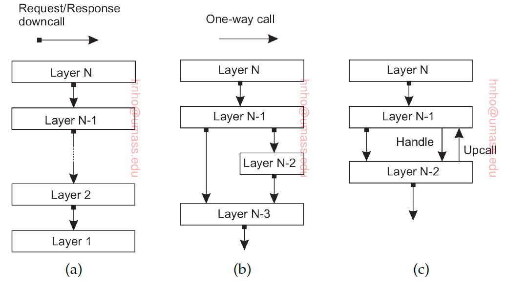
Each layer uses previous layer to implement new functionality that is exported to the layer above. In DS, different layers reside in different servers (Multi-tier web apps). We can see this as Layer_N is the client for Layer N-1 which is the client for Layer N-2 etc. There can special situtaions when lower layer do an upcall to its higher layer. Each layer offers interfaces that can be called and hide away the actual implementation of the service.
Object-based Style
Each objects corresponds to a component. Each component correspond to a procedure. These components are connecteed via Remote Procedure Call (RPC). Interfaces offered by objects abstract away the implementation details.
In case of DS, each objects reside in different servers, i.e. the caller and the callee need not to be executed on the same machine, so a procedure call take place over a network
Difference with REST is that Object-based Style has language support.
Advantages: Provide a natural way of encapsulating data (object’s state) and the operations that can be performed on that data (object’s method). Novel sequence of communications compared to layer design.
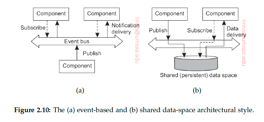
Event-based Architecture
Referential coupling: explicit referencing in communication, a process can communicate only if it knows the name or the identifier of the other process it wants to exchange information with
Temporal coupling: processes that are communicating need to be up and running
Publisher-Subscriber paradigm: processes have no explicit reference to each other
Event-based: referential decoupling + temporal coupling
Publishers publish events. Subscribers subscribe to types of events. Once published by any publisher, event is delivered to the processes that subscribe to it. It’s generally required that the subscriber is up-and-running at the time the event is published.
Shared-data Space
referential decoupling + temporal decoupling
Publisher publish to the shared (persistent) data space and the subscriber picks up data from the data space.
Decoupled in space and time (because Publisher and Subscriber are in different servers and don’t have to explicit reference each other, and Publishers and Subcribers don’t have to be active at the same time). In Client-server architecture, client and server need to be active at the same time.
Resource-oriented Architecture
Example is REST: (Representational State Transfer).
- A list of resources identified via a naming schme
- All servers offer the same interface (HTTP - consisting of four operations)
- Messages are fully described
- No state of the caller is kept (stateless execution), i.e., after executing an operation, components forget everything about the caller
Example: S3 uses HTTP for API https://bucketname.s3.aws.com/objName HTTP operations: GET/PUT/DELETE/POST
Return JSON objects
System Architectures
Client-Server Architectures
Centralized organization
Synchronous
A server is a process implementing a specific server, a client is a process that requests service from the server by sending it a request and subsequently waiting for the server’s reply.
Client-Server interfaces can be at different layers:
- User-interface level
- Processing level
- Data level
One of the main issues was how to draw a distinction between a client and a server. Simplest organization:
- A client machine containing only the programs implementing (part of) the user-interface
- A server machine containing processing and data level
Divide machines into client machines and server machines. Two-tier architecture:
Edge-Server Systems
Edge Servers: from client-server to client-proxy server
These systems are deployed on the Internet where servers are placed “at the edge” of the network. This edge is formed by the boundary between enterprise networks and the actual Internet, for example, as provided by an Internet Service Provider (ISP). Likewise, where end users at home connect to the Internet through their ISP, the ISP can be considered as residing at the edge of the Internet.
Content distribution networks: proxies cache web content near the edge
For example, when we go on Google, the image isn’t coming from the central Google server, but actually comes from an edge server. Content are distributed to the edge servers (Cache management lets we know where to pick up content).
Decentralized Architectures: Structured P2P
All servers are equal, functionalities need to carried out by every processes that constitute the distributed system. Much of the interaction between processes is symmetric: each process will act as a client and a server at the same time.
Peer-to-peer architectures evolve around the question how to organize the processes in an overlay network.
Structured Overlay network: a virtual network to connect these peers, peers use the overlay network to decide which peer to talk to. Each peer keep a pointer some nodes/peer. In a number of steps, it’s guaranteed we can find the item we need. Structure Overlay network adheres to a specific, deterministic topology: a ring, a binary tree, a grid, etc. This topology is used to efficiently look up data.
Structured peer-to-peer system is generally based on using a semantic-free index, which means each data item that is to be maintained by the system, is uniquely associated with a key, and that this key is subsequently used as an index. To this end, it is common to use a hash function, so that we get:
key(data item) = hash(data item’s value)
Chord: structured peer-to-peer system
- Use a distributed hash table to locate objects
- Data item with key k is stored in the smallest node with id >= k
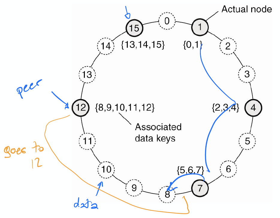
With structured peer to peer system, we can look up a data item by mean of its key.
Content Addressable Network (CAN)
CAN: d-dimensional coordinate system
- Parititioned among all nodes in the system
- Every data item mapped to a point
Can have an arbitrary lookup with CAN (not only by key)
Decentralized Architectures: Unstructured P2P Systems
- Topology based on randomized algorithms
- When a node joins it often contacts a well-known node to obtain a starting list of other peers in the system. This list can then be used to find more peers, and perhaps ignore others, and so on.
- Each node pick a random set of nodes and becomes their neighbors
- Each node/server need to keep information about its neighbors, just randomly visit a node
- Choice of degree can impact the network
- Can be used for file sharing
- Simple but can take some time to find item in the system (won’t scale very well) because unlike structured peer-to-peer systems, looking up data cannot follow a predetermined route when lists of neighbors are constructed in an ad hoc fashion. We need to resort to searching for data
- Unstructured P2P do not scale
Searching for data
- Flooding: an issuing node u simply passes a request for a data item to all its neighbors. If v has the required data, it responses directly or send it back to u. If v does not have the requested data, it forwards the request to all of its own neighbors. Flooding is very expensive, and thus, a request often has an associated time-to-live or TTL value, giving the maximum number of hops a request is allowed to be forwarded.
- Random Walk: an issuing node u can simply try to find a data item by asking a randomly chosen neighbor, say v. If v does not have the data, it forwards the request to one of its randomly chosen neighbors, and so on. A random walk imposes much less network traffic but may take much longer for searching data. To decrease the waiting time, an issuer can simply start n random walks simultaneously
Variant:
- Can build structured network using unstructured overlay
- The bottom layer is a random overlay and the top layer is a structured overlay
Decentralized Architectures: Hierarchical P2P Systems
SuperPeers: Some nodes becomes “distinguished” and take on the responsibility for coordination.
Every regular peers is connected as a client to a SuperPeer. All communications from and to a regular peer proceed through that peer’s associated super peer. Have an overlay network on the set of SuperPeers. SuperPeers are expected to be long-lived processes with high availability.
Hybrid: Centralized + P2P
Example: BitTorrent
- Collaborative P2P downloads, client-server for lookups
- Meta data is kept by the centralized node, the actual data is kept by the nodes
- To download the file, user access a global directory, such directory contains reference to torent files
- A torent file contain a link to a tracker, which is server keeps account of active nodes that have the requested files
- Download a chunk of files from other users until the downloaded chunks can be assembled together yielding the complete file
Lecture 3: Background: Thread and Process
Lecture 4: Virtualization, Container and Serverless
Virtualization
- Emulation
- Virtual Machine emulates/simulates complete hardware
- Full/Native Virtualization
- VM simulates just some aspects of hardware/OS
- Example: VMWare, VirtualBox
Hypervisors
- Hypervisors/VMM: Layer implementing virtualization
- Resource management, isolation, scheduling
- Two types of hypervisors:
- Type 1: hypervisors runs on “bare mental:
- Type 2: hypervisors runs on a host OS
- Guest OS runs inside hypervisors
- Both hypervisors act like real hardware, but hypervisors only has permission for resource management, and access isolation
Type 1 Hypervisor
- Hypervisor is the real kernel, run on kernel model
- The guest OS is running on user mode, (while it thinks it runs on Kernel mode)
- If guest OS performs the priviledge instructions, trap and switch control to the real kernel mode
Q: Is VirtualBox type 1 or type 2?
A: Type 2
Type 2 Hypervisor
- Run on user mode
- VMWare for example
- When the guest VM loads a program, Virtual Machine Manager scan its blocks and replaces privileged instructions with VMM-lelvel code on the fly
- The binary translation is to have the guest OS calls the hypervisors
- VMM level code either emulates privleged instructions or performs system calls
- Keep a cache of modified block (so as to not scan over and over again)
Paravirtualization
- Modify OS kernel code
- Run in kernel mode
- Replace all privileged instruction calls with hypercalls
- OS behaves like a user program making system calls and hypervisor executes the priviledge operations invoked by hypercall
Containers
Only one OS, so a little less isolation, because all containers share the samne kernel. Faster to provision because OS is already up. Containers have the illusion that they run in isolation.
Serverless
Distributed platform runs functions inside a container:
- Single threaded code
- Stateless: data must be fetched from external storage
Lecture 5: Server Design
Server Design
Iterative vs Concurrent Server
To locate a server endpoint: use a directory service where the server can register itself
Each tiered level may be replicated and load is balanced across the clusters through a dispatcher which assigns each incoming request to a server in the cluster.
There are two methods for request assignment in clusters: Round Robin, Session Based (requests from a user session are routed to the same session to maintain state about that session)
Client establishes a TCP connection with the Switch node that is the front node. Switch will then make a TCP connection with an actual server and will forward client’s request to that server. Switch acts as an intermediate node that will basically receive requests from the client and will relay them to an actual server. When server sends the reply, it sends the reply with IP address of the Switch, so the client doesn’t know that the response actually came from a third machine.
Server Architecture
Four types of architecture:
- Sequential: Single thread execution, handle one request at a time
- Event-Based: Single thread execution, able to handle interrupt. Using asynchronous communication to serve multiple requests at a time
- Thread-based: Multi-threaded execution, one thread per request
- Process-based: Multi-process execution, one process per request
Question: Which one is more resource efficient?
A: If have one core, then event-based
If have multi-core, then thread-based
Event-based can lead to convoy effect (phenomenon associated with the First Come First Serve (FCFS) algorithm, in which the whole Operating System slows down due to few slow processes.) if computation for one request takes too long to run.
Can combine thread-based and event-based
Scalability
- Scale up
- Scale out
- Ship code instead of data (Rather than you sending data to the computation for execution, the computation will come where the data is present and will then execute. Example: Search Engine)
- Cache
Migration
Example of “Ship code instead of data”
-
Process migration: Also known as strong mobility, this includes the migration of all the components of a process i.e. code segment, resource segments and execution segment. An active process (an already executing program) on a machine is suspended, its resources like memory contents and register contents are migrated over to the new machine and then the process execution is restarted.
-
Code migration: Also known as weak mobility. In this model only the code is migrated and the process is restarted from the initial state on the destination machine. Example: Docker
Lecture 6: Communications in Distributed System
Communication Models
Client pull architecture: Clients pull data from servers by sending requests.
Pros: Server need not maintain state information(stateless), more resilient to failures or easy failure handling
Cons: Scalability problem (one reason is the overhead cause by lot of messages being exchanged; every response requires a request to go the server ), fault tolerance.
Server push architecture: Servers push data to clients.
Pros: Relatively more scalable (one reason is because the client doesn’t have to continuously poll the server for fresh data and the server automatically pushes when new data arrives).
Cons: Servers have to maintain client state information, less resilient to failures.
Q: Which one to choose depends on when/how-often to push and pull?
A: When servers and client interact frequently: server-push (because more scalable). Example: Streamming Service
When servers and client interact now and then: client-pull
Remote Procedure Calls
Goal: Make distributed computing look like centralized computing. Allow remote services to be called as procedures
When a process in machine A calls a procedure in machine B, the calling process in A is suspended, and execution of the called procedure takes place on B. Information can be transported from the caller to the callee in the parameters and can come back in the procedure result. No message passing at all is visible to the programmer.
Parameter Passing
-
Local procedure parameter passing: Call-by-value, Call-by-reference
-
RPC only supports call-by-value:
- Stubs takes care of packing arguments in neutral format and sending message
- Client makes a local procedures call to client stub
- Stub - proxies transform local call to remote call
- Flattening - marshalling, copying all the parameters needed to run to the server, making parameter passing look transparent
- Different machines have different data format. Solution: Use External Data Representation
- Stubs takes care of packing arguments in neutral format and sending message
Case Study: SUNRPC